As TROOPERS15 has come to an end, I’ve finally got the time and energy to give you a deeper insight into the TR15 badge. As most of you have probably heard during the conference, this year’s badge was based on the OpenPCD2. The OpenPCD 2 is a 13.56MHz NFC Reader, Writer and Emulator under the GNU GPL v2. As NFC is, yet again, on an uprise, a badge with NFC simply gives you the chance to fiddle around and hack stacks of stuff in the real world. Adding some TROOPERS spirit and a few little secrets we hope we’ve designed a pretty nice badge!
What Can It Do?
To start with, it’s just an active NFC tag. When you connect the USB port to a power source, it will start up and emulate your very own and personal TR15 challenge ID. I guess you will have already used that during the con. Now, when you’ve already added the buttons, and you press the button at three, three times, both the LEDs four and five will glow. You’re now in LibNFC mode. Using NFC tools you can now read (use nfc-mfclassic or nfc-mfultralight) basic NFC cards and tokens from your computer. Above that there are many more fun things (like mifare classic cracking) you can do with the badge.
HARDware
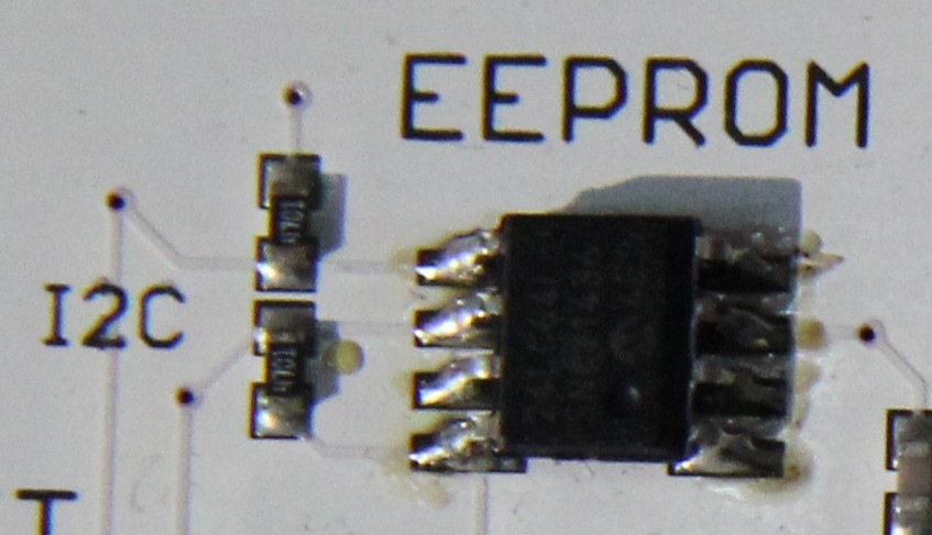
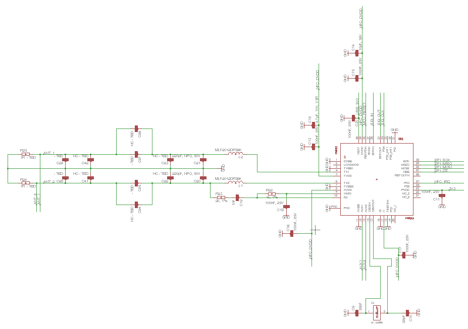
The badge uses a NXP PN532 for the NFC interface. It is connected to the LPC 1342 microcontroller via SPI, which yet again offers connectivity via USB and the UART debugging interface. For convenience we’ve used seven free IO pins to add some extra interfacing to the whole device. All these pins can be populated with either a pushbutton or a LED. Above that the pins one and two can be used for an I2C serial EEPROM, to give you some persistent storage. For the original TR15 firmware, you would need a pushbutton on three and seven and LEDs on four, five and six.
The PCB
The schematics and layout will follow, soon, after having been slightly redesigned. The TR15 badges will stay an original!
Soldering
During the conference, all attendees had the chance to do a little soldering. If you would like to finish the badge on your own you will need three resistors (0603 – 200Ohm), three LEDs (0603) and two pushbuttons (SMD). If you would like to add our debugging parts, too, you will need to extra pushbuttons and a pin-head (6 pins).
- Add a resistor between the middle pads (right in the middle) at the markings 4, 5 and 6.
- Add a LED between the two pads close to the antenna ad the markings 4, 5 and 6. Minus/GND points towards the antenna.
- Add pushbuttons at the markings 3 and 7.
A little help:

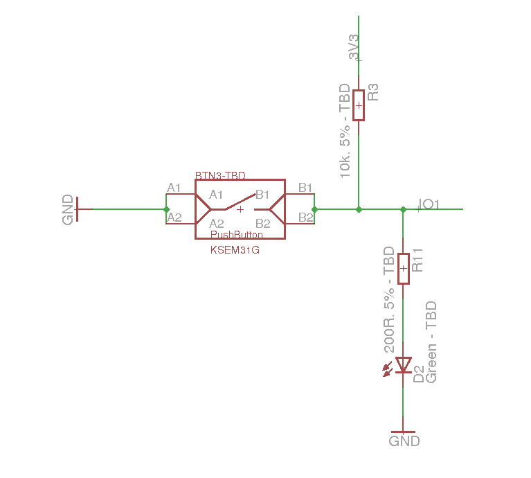
Above that the following sketch shows how each one of the pushbutton / LED combinations is actually connected to the microcontroller.
Although you have pads for both an LED (with a resistor in series) and a pushbutton (with a pull-up) at each marking, one marking is connected to one single IO pin on the controller. So you should decide to either use the LED or the pushbutton.
Firmware
The firmware, yet again, is basically the original OpenPCD 2 libNFC firmware, which was extended by a very shy person who is ashamed that it didn’t work out 100 % (He’s the one who wrote this section, I’m just quoting here).
Actually libnfc is not the only Operation Mode. You also have an inbuilt (not quite standard-conform) read and emulation functionality. The “read” function enables you to read the first Block of a Mifare Ultralight but also a Mifare Classic if the key “FFFFFF FFFFFF” is used. The “emulate” takes the previously read block and announces it as its own first block, this way you are able to exchange data between two badges.
Due to various problems with this authentication-process the emulation part is considered to be not operational with a third party nfc-reader or libNFC. So you can take the badge, hold it next to an NFC token (or another badge), press one button to read data, and then replay it to another badge or our terminal, and maybe to misbehaving readers.
All three parts (libnfc, read, emulate) from the firmware are more or less identical to parts of the OpenPCD 2 project – which is where the credit should go to.
Basic use:
- Install libNFC (When building you will need: ./configure –sysconfdir=/etc –prefix=/usr –with-drivers=pn532_uart )
- Create config file (/usr/local/etc/nfc/libnfc.conf OR /etc/nfc/libnfc.conf) (Further information on config file )
- device.name = “badge”
- device.connstring = “pn532_uart:/dev/ttyACM3”
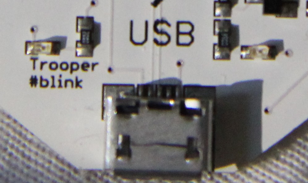
- Connect the badge to a PC using a microUSB cable (not the one from the powerbank!!). Press the button at three three times, and both the LEDs four and five should be switched on.
- Run nfc-list and your badge will be up and running
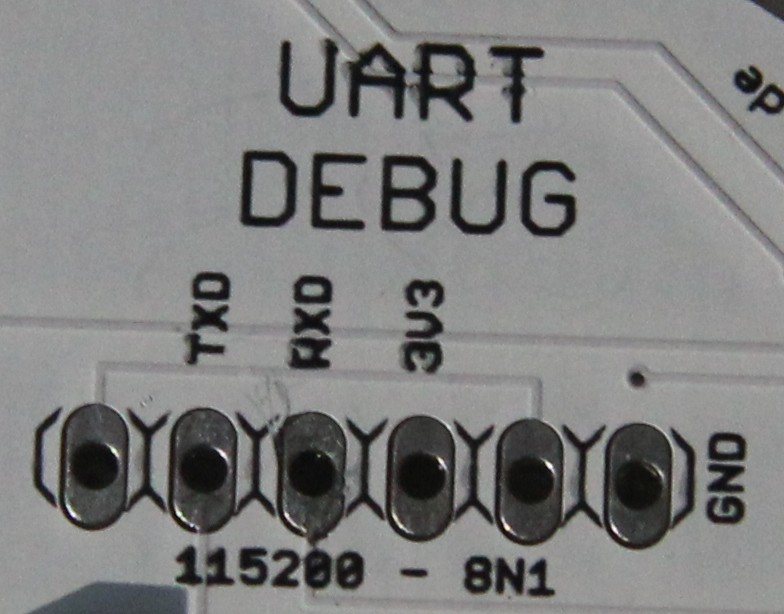
If you really want to go for it, you should add the pin header for the debugging interface! It’s worth it!
A few Constraints
The PN532 can only emulate four byte UIDs when emulating an NFC tag, where the first byte is hardcoded. So emulating arbitrary NFC tags is a little bit more complicated. In theory you can do a little bit of magic: You might establish an RF channel to the target device (by using the standard functions within the PN532) and then cut power to the chip. The target device will now be waiting for transmission of the UID, so if you repower the PN532 and send an arbitrary data package, you can transmit seven byte UIDs. I haven’t seen this approach in use, yet, but it should work!
What Next?
Feel free to browse our GitHub Repo and have a closer look at the firmware. You can easily change the default mode to libNFC, so that you can directly use it on your computer, right after connecting it! If you want to flash the badge, you just have to short the top and bottom pins on the ISP pushbutton (well, the solder pads) and then connect the USB cable. The badge should now come up as a USB mass storage device and can be flashed as any other LPC1342. For a quick start, there is a small tool in the repo.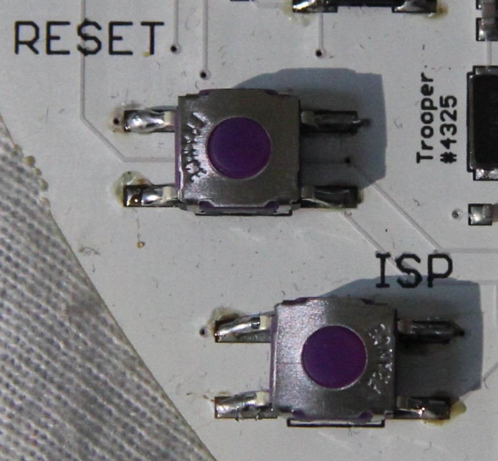
Many Thanks
Many thanks to all attendees who’ve already given the badge a try and have soldered during TROOPERS!
Above that many thanks to the “very shy person”, who in my opinion, and I guess in yours, too, has done an awesome job on the firmware!
Yours truly
BadgeWizard
is it possible to post a list of the needed electronic parts. I would like to finish the badge at home.
Thank You 🙂
Hi,
I’ve just added some data on the parts we had in the soldering corner and some further details on the schematics.